 |
S.r.l. |
tel.095.7188068 cell.368.3760845 


ULTIMI ARRIVI
Prodotti per
TELECOMUNICAZIONI
GSM / DCS /
PCS / MS Test Set
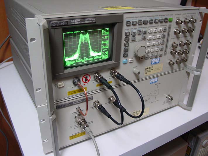
HP 8922M +
HP83220E (option 010)
RFgenerator,
RFAnalyzer, Spectrum Analyzer, Digital Oscilloscope,
Audio Analyzer,
AudioSource, ReferenceOscillator for GSM 900,DCS1800,PCS1900.
----------
RFGenerator 10-1000MHz res1Hz Output- 127- -16dBm, GSM modulation,
Pulse modulation, RFanalyzer 10-1000MHz res1Hz, GMSK Analog FM/pulse,
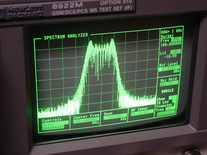
Spectrum Analyzer 10-1000MHz Dynamic 80dB Marker Span10KHz,
DigitalOscilloscope 2Hz-50KHz Sweep 10u-100ms,
AudioAnalyzer 20Hz-400KHz
Max30V DC 100mV-42V
THD+Noise1KHz +- 5Hz Sinad1KHz +- 5Hz
AudioSource DC-25KHz 0.1mV-4Vrms I-BASIC Memory-Card.
----------
HP83220E Test for Mobile and BaseStation DCS1800,PCS1900
-foto indicativa-
caratteristiche e manuali


Quick Start Guide for using the
HP8922H/M/P/S GSM Test Set
1) Before you plug in the HP8922 or the HP83220E, check the rear AC
input voltage setting. Units from the USA are usually set to 120VAC and
can be changed here to 240 VAC, etc.
2) Set the HP8922 on top of the HP83220E and connect the cables on the
rear of the unit(s). You need to install (3)BNC jumper cables and (1)
15 connector data cable from the HP8922 to the HP83220E as follows:
HP8922 to HP83220E
AM - AM
Scope - Scope
10 Mhz Ref out - 10 Meg Ref in
PNC (15 contact din) - PNC (15 contact din)
3) On the front of the units, connect the 2 BNC cables from the
AUX RF out to the AUX RF in of the units. Connect the 6" SMA
cable from the RF Link Port of the HP8922 to the SMA connector
on the HP83220E. This system that includes the HP8922M with an
HP83220E and uses an sma to sma link port cable cable is called
an HP8922P system.
4) After making sure the rear AC voltage input(s) are set to the
correct AC input, plug in the 83220E and the 8922 and turn on
the system by pressing the front Power button on the HP8922.
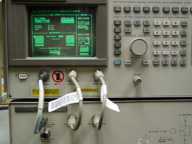
5) The display should come on in the "CELL STATUS" screen. If
it does not, you MUST check to see if the 8922P system is in the
wrong compatability mode. This occurs because they are left in
this mode when they are calibrated. Scroll to the Configure
screen by using the curser control knob to scroll to the lower
right to "more" select it (
select by pressing in and letting go on the curser
control knob) now scroll to "configure" . Select "configure"
and scroll to "compatible" and select
8922P ( 8922P
must be underlined). Now press "CALL CNTL" on the top row of
buttons. You will get the "CALL STATUS" screen.
6) The GSM Phone is connected to the HP8922P system using the RF
IN/OUT (type N) connector at the lower left side of the 83220
unit. The coupled RF I/O connector on the right lower side
should be terminated with a 50 ohm load. Do not connect the
phone to any other connectors as damage could result. The RF IN
/ OUT connector is used for all RF tests with the GSM phone on
all bands. You will need a cable with RF coupler to connect the
antenna of the GSM phone to the IN/OUT connector. These are
supplied by the cell phone or test equipment (manufacturers).
One such coupler is the Acterna model 330. It is a desk top pad
with cable that goes to the 8922P system IN/OUT. Nokia has test
cables to go from the phone antenna connector directly to the
8922P (83220E In/Out). The GSM phone is turned on with a TEST
sim card installed or the GSM phone must be in an RF Isolation
enclosure to insure it will not try to work with any local cell
sites. The Test Sim Card makes the phone work on channels and
systems that are not in use worldwide. If you use an isolation
enclosure, you can test the phone with any sim card.
7) With the GSM phone on, scroll to the Operating Mode on the "Cell
Status" screen and select the mode (GSM900, E-GSM, DCS1800 or
PCS1900) of your phone. Leave the bottom portion of the mode in
" Active Cell". This will automatically test the phone. Wait for
the phone to indicate it has signal level or service. You may
need to increase the Amplititude depending on the antenna
coupler you are using for that particular phone. Start the test
by pressing the "ORG CALL" button. This will make the 8922P
system call your phone and may be the easiest way to start.
When the phone rings, press the answer button on the phone. You
can also press "RCV CALL"- this will allow you to make a call
with your GSM phone to start the test. Once the call is made,
in the upper left of the 8922P screen, "CONNECTED" will appear.
You can now check or view your phone performance by scrolling to
and selecting your choice of
PHASE FERQUENCY, POWER RAMP, BIT ERROR, PEAK POWER, SPECTRUM
ANALYZER, SCOPE AND AUDIO.
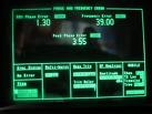
CELL STATUS Screen here,
you can set the "TX Level" on the left side of the screen. The
8922P allows you to set and view 15 power levels for the GSM
phone. We found power level 0 to make the phone output +30 dbm
or 1 watt; power level 10 was +10 dbm or 10
mW and power level 15 to
be 0 dbm or 1 mW. Return
the power level to 10 after checking power level control. Once
again, the power level you see will depend on the loss of your
antenna coupler. Our test used a coupler with a direct
connection to the antenna of the phone.
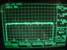
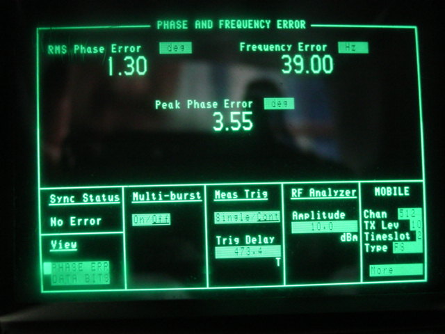
Phase and Frequency Screen
PHASE FREQUENCY-, you can
view the phase frequency and frequency errors. You can return
from any test to the Cell Status screen by pressing the "CELL
CNTL" button.
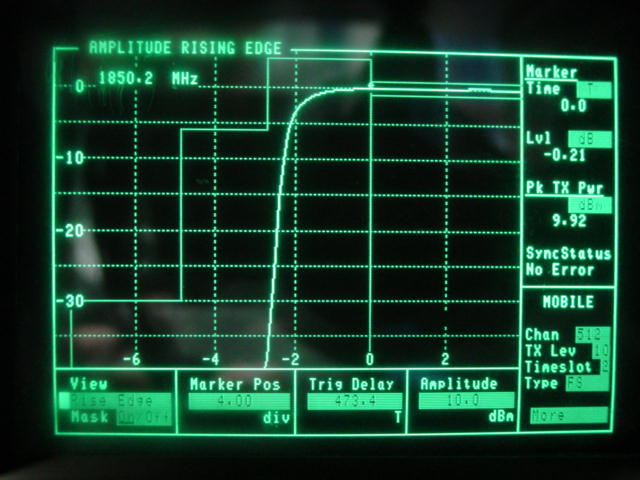
Power Ramp Screen with Leading
Edge and Top 2 db viewed
POWER RAMP - view the
leading , trailing edge or top 2 db of the power ramp. Change
the time slot on the lower left of the screen to view each power
ramp in each time slot. (return by pressing "CELL CNTL")
BIT ERROR - view bit
error as a percentage.
PEAK POWER - view peak
power.
Spectrum Analyzer Test Screen
SPECTRUM ANALYZER - Here
you can view the Spectrum Analyzer of the 8922 set to the output
frequency of the phone. Here , you can change the Mobile channel
while viewing the spectrum.
Oscilloscope viewing audio on "SCOPE" Screen
SCOPE - View the mobile
phone audio on this oscilloscope display.
AUDIO - This sets up an
audio delay so you can hear your audio from the mic to the
earpiece with a 0.5 second (adjustable to 5 seconds) delay. You
see the audio level on the display.
Many of the variables on the screen can be adjusted in the
different test views. Save your screen setup by pressing "SHIFT"
then "SAVE" and use 8 digits to lable your saved screen. The
next time you turn on the 8922, press "RECALL" and select your
saved screen. If you save a screen with "POWERON" , that screen
will come on every time you power on the 8922. End your call
by pressing End on your phone and then "END CALL" on the 8922.
Most of thee screens will allow you to select "HELP" so you can
get help from the help screen(s).
Euro
540,00
(completo di cavi rf e PCN Interface)
Disponibili manuali
MATERIALE IN PRONTA
CONSEGNA OFFERTA LIMITATA

